|
SPECIFIC OUTCOME 1: Review the requirements for database access for a computer application using SQL. |
|
ASSESEMENT CRITERIA |
|
v 1. The review identifies and explains the feasibility of the requirements. v 2. The review identifies the database access objectives and critical performance factors. v 3. The review estimates the development effort required so that the cost may be estimated. v 4. A review procedure is adopted, which ensures that the outcomes meet the database access requirements. |
1.1 A database is an organized collection of data. The data are typically organized to model aspects of reality in a way that supports processes requiring this information. For example, modelling the availability of rooms in hotels in a way that supports finding a hotel with vacancies.
Database languages are special-purpose languages, which do one or more of the following:
- Data definition language– defines data types and the relationships among them
- Data manipulation language– performs tasks such as inserting, updating, or deleting data occurrences
- Query language– allows searching for information and computing derived information
- Abstraction
Is the process of separating ideas from specific instances of those ideas at work. Computational structures are defined by their meanings (semantics), while hiding away the details of how they work. Abstraction tries to factor out details from a common pattern so that programmers can work close to the level of human thought, leaving out details which matter in practice, but are immaterial to the problem being solved. For example, a system can have several abstraction layers whereby different meanings and amounts of detail are exposed to the programmer; low-level abstraction layers expose details of the computer hardware where the program runs, while high-level layers deal with the business logic of the program.
Abstraction captures only those details about an object that are relevant to the current perspective; in both computing and in mathematics, numbers are concepts in programming languages. Numbers can be represented in myriad ways in hardware and software, but, irrespective of how this is done, numerical operations will obey identical rules.
Abstraction can apply to control or to data: Control abstraction is the abstraction of actions while data abstraction is that of data structures.
- Control abstraction involves the use of subprogramsand related concepts control flows
- Data abstraction allows handling data bits in meaningful ways. For example, it is the basic motivation behind data type.
One can regard the notion of an object (from object-oriented programming) as an attempt to combine abstractions of data and code.
The same abstract definition can be used as a common interface for a family of objects with different implementations and behaviours but which share the same meaning. The inheritance mechanism in object-oriented programming can be used to define an abstract class as the common interface.
The recommendation that programmers use abstractions whenever suitable in order to avoid duplication (usually of code) is known as the abstraction principle. The requirement that a programming language provide suitable abstractions is also called the abstraction principle.
1.1.2 Data Independence
Data independence can be explained as follows: Each higher level of the data architecture is immune to changes of the next lower level of the architecture.
The logical scheme stays unchanged even though the storage space or type of some data is changed for reasons of optimization or reorganization. In this external schema does not change. In this internal schema changes may be required due to some physical schema were reorganized here. Physical data independence is present in most databases and file environment in which hardware storage of encoding, exact location of data on disk, merging of records, so on this are hidden from user.
One of the biggest advantages of database is data independence. It means we can change the conceptual schema at one level without affecting the data at other level. It means we can change the structure of a database without affecting the data required by users and program. This feature was not available in file oriented approach.
Data Independence Types
The ability to modify schema definition in one level without affecting schema definition in the next higher level is called data independence. There are two levels of data independence, they are Physical data independence and Logical data independence.
- Physical data independence is the ability to modify the physical schema without causing application programs to be rewritten. Modifications at the physical level are occasionally necessary to improve performance. It means we change the physical storage/level without affecting the conceptual or external view of the data. The new changes are absorbed by mapping techniques.
- Logical data independence is the ability to modify the logical schema without causing application program to be rewritten. Modifications at the logical level are necessary whenever the logical structure of the database is altered (for example, when money-market accounts are added to banking system). Logical Data independence means if we add some new columns or remove some columns from table then the user view and programs should not changes. It is called the logical independence. For example: consider two users A & B. Both are selecting the empno and ename. If user B add a new column salary in his view/table then it will not affect the external view user; user A, but internal view of database has been changed for both users A & B. Now user A can also print the salary. It means if we change in view then program which use this view need not to be changed.
Logical data independence is more difficult to achieve than physical data independence, since application programs are heavily dependent on the logical structure of the data that they access.
- Data manipulation language(DML)
Is a family of syntax elements similar to a computer programming language used for selecting, inserting, deleting and updating data in a database. Performing read-only queries of data is sometimes also considered a component of DML.
A popular data manipulation language is that of Structured Query Language (SQL), which is used to retrieve and manipulate data in a relational database.[1] Other forms of DML are those used by IMS/DLI, CODASYL databases, such as IDMS and others.
Data manipulation language comprises the SQL data change statements,[2] which modify stored data but not the schema or database objects. Manipulation of persistent database objects, e.g., tables or stored procedures, via the SQL schema statements rather than the data stored within them, is considered to be part of a separate data definition language. In SQL these two categories are similar in their detailed syntax, data types, expressions etc., but distinct in their overall function.
Data manipulation languages have their functional capability organized by the initial word in a statement, which is almost always a verb. In the case of SQL, these verbs are:
The purely read-only SELECT query statement is classed with the ‘SQL-data’ statements and so is considered by the standard to be outside of DML. The INTO form is considered to be DML because it manipulates (i.e. modifies) data. In common practice though, this distinction is not made and SELECT is widely considered to be part of DML.
Most SQL database implementations extend their SQL capabilities by providing imperative, i.e. procedural languages. Examples of these are Oracle‘s PL/SQL and DB2‘s SQL_PL.
Data manipulation languages tend to have many different flavours and capabilities between database vendors. There have been a number of standards established for SQL byANSI, but vendors still provide their own extensions to the standard while not implementing the entire standard.
Data manipulation languages are divided into two types, procedural programming and declarative programming.
Data manipulation languages were initially only used within computer programs, but with the advent of SQL have come to be used interactively by database administrators.
- Data model
Is used in two related senses. In the sense covered by this article, it is a description of the objects represented by a computer system together with their properties and relationships; these are typically “real world” objects such as products, suppliers, customers, and orders. In the second sense, covered by the article database model, it means a collection of concepts and rules used in defining data models: for example the relational model uses relations and tuples, while the network uses records, sets, and fields.
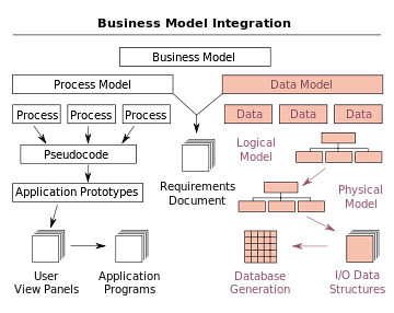
Overview of data modelling context: Data model is based on Data, Data relationship, Data semantic and Data constraint. A data model provides the details of information to be stored, and is of primary use when the final product is the generation of computer software code for an application or the preparation of functional to aid a computer software make-or-buy decision. The figure is an example of the interaction between process and data models.
Data models are often used as an aid to communication between the business people defining the requirements for a computer system and the technical people defining the design in response to those requirements. They are used to show the data needed and created by business processes.
A data model is a way finding tool for both business and IT professionals, which uses a set of symbols and text to precisely explain a subset of real information to improve communication within the organization and thereby lead to a more flexible and stable application environment.
A data model explicitly determines the structure of data. Data models are specified in a data modelling notation, which is often graphical in form.
A data model can be sometimes referred to as a data structure, especially in the context of programming languages. Data models are often complemented by function models, especially in the context of enterprise models.
|
SPECIFIC OUTCOME 2 : Design database access for a computer application using SQL. |
|
ASSESEMENT CRITERIA |
|
v 1. The design implements user requirements. v 2. The design of the database structure resembles the output from the data analysis. v 3. The structure of each table in the database adheres to the third normal form. v 4. The methods of accessing the data are identified. v 5. The key relationships between the tables within the database are identified. v 6. The data types for primary and foreign keys are consistent throughout the database. |
2.1 Simple indexes
Given the fundamental importance of indexes in databases, it always comes as a surprise how often the proper design of indexes is neglected. It often turns out that the programmer understands detail, but not the broad picture of what indexes do. Bob Sheldon comes to the rescue with a simple guide that serves either to remind or educate us all!
One of the most important routes to high performance in a SQL Server database is the index. Indexes speed up the querying process by providing swift access to rows in the data tables, similarly to the way a book’s index helps you find information quickly within that book. In this article, I provide an overview of SQL Server indexes and explain how they’re defined within a database and how they can make the querying process faster. Most of this information applies to indexes in both SQL Server 2005 and 2008; the basic structure has changed little from one version to the next. In fact, much of the information also applies to SQL Server 2000. This does not mean there haven’t been changes. New functionality has been added with each successive version; however, the underlying structures have remained relatively the same. So for the sake of brevity, I stick with 2005 and 2008 and point out where there are differences in those two versions.
Index Structures
Indexes are created on columns in tables or views. The index provides a fast way to look up data based on the values within those columns. For example, if you create an index on the primary key and then search for a row of data based on one of the primary key values, SQL Server first finds that value in the index, and then uses the index to quickly locate the entire row of data. Without the index, a table scan would have to be performed in order to locate the row, which can have a significant effect on performance.
You can create indexes on most columns in a table or a view. The exceptions are primarily those columns configured with large object (LOB) data types, such as image, text, and varchar(max). You can also create indexes on XML columns, but those indexes are slightly different from the basic index and are beyond the scope of this article. Instead, I’ll focus on those indexes that are implemented most commonly in a SQL Server database.
An index is made up of a set of pages (index nodes) that are organized in a B-tree structure. This structure is hierarchical in nature, with the root node at the top of the hierarchy and the leaf nodes at the bottom, as shown in Figure 1.

Figure 1: B-tree structure of a SQL Server index
Index Design
As beneficial as indexes can be, they must be designed carefully. Because they can take up significant disk space, you don’t want to implement more indexes than necessary. In addition, indexes are automatically updated when the data rows themselves are updated, which can lead to additional overhead and can affect performance. As a result, index design should take into account a number of considerations.
Database
As mentioned above, indexes can enhance performance because they can provide a quick way for the query engine to find data. However, you must also take into account whether and how much you’re going to be inserting, updating, and deleting data. When you modify data, the indexes must also be modified to reflect the changed data, which can significantly affect performance. You should consider the following guidelines when planning your indexing strategy:
- For tables that are heavily updated, use as few columns as possible in the index, and don’t over-index the tables.
- If a table contains a lot of data but data modifications are low, use as many indexes as necessary to improve query performance. However, use indexes judiciously on small tables because the query engine might take longer to navigate the index than to perform a table scan.
- For clustered indexes, try to keep the length of the indexed columns as short as possible. Ideally, try to implement your clustered indexes on unique columns that do not permit null values. This is why the primary key is often used for the table’s clustered index, although query considerations should also be taken into account when determining which columns should participate in the clustered index.
- The uniqueness of values in a column affects index performance. In general, the more duplicate values you have in a column, the more poorly the index performs. On the other hand, the more unique each value, the better the performance. When possible, implement unique indexes.
- For composite indexes, take into consideration the order of the columns in the index definition. Columns that will be used in comparison expressions in the WHERE clause (such as WHERE FirstName = ‘Charlie’) should be listed first. Subsequent columns should be listed based on the uniqueness of their values, with the most unique listed first.
- You can also index computed columns if they meet certain requirements. For example, the expression used to generate the values must be deterministic (which means it always returns the same result for a specified set of inputs)..
2.2 Queries
Another consideration when setting up indexes is how the database will be queried. As mentioned above, you must take into account the frequency of data modifications. In addition, you should consider the following guidelines:
- Try to insert or modify as many rows as possible in a single statement, rather than using multiple queries.
- Create no clustered indexes on columns used frequently in your statement’s predicates and join conditions.
- Consider indexing columns used in exact-match queries.
2.3 Multi-Level Indexes
The indexing described so far involve ordered index files. A binary search is applied to the index to locate pointers to disk blocks or records in the file having a specific index field value.
Remember from before, a binary search requires log2bi block accesses for an index with bi blocks. Each step of the binary search reduces the part of the index file we search by a factor of 2. (Each step divides the search space by 2, or halves the search space)
With multilevel indexes, the idea is to reduce the part of the index that we continue to search by a larger factor, the blocking factor of the index, where the bfri is greater than 2. The blocking factor of the index, bfri is called the fan-out, or fo of the multilevel index.
Searching a multilevel index requires approximately (logfobi) block accesses which is a smaller number than for a binary search if the fan-out is larger than 2. If the fan out is equal to 2, there is no difference in the number of block accesses.
The index file is called the first level of a multilevel index. It is an ordered file with a distinct value for each key value K(i). Therefore we can create a primary index for the first level. This index to the first level is called the second level of the multilevel index.
The second level is a primary index, therefore we can use block anchors, and the second level has one entry for each block in the first level index. The blocking factor for all other levels is the same as for the first level, because the size of each index entry is the same. Each entry has one field value, and one block address.
If the first level has r1 entries, and the blocking factor (which is also the fan out) for the index is bfri = fo, then the first level needs ér1/foù blocks, which is therefore the number of entries r2 needed at the second level of the index.
If necessary, this process can be repeated at the second level. The third level, which is an index for the second level, has an entry for each second level block, so the number of third level entries is r3 = ér2/foù.
We only require a second level only if the first level needs more than one block of disk storage, and we require a third level only if the second level requires more than one block as well.
This process can be repeated until all the index entries at some level t fit in a single block.
The block at the tth level is the top-level index. Each level reduces the number of entries from the previous level by a factor of fo (the index fan out or blocking factor of the index).
A multilevel index with r1 first level entries will have approximately t levels, where:
t = élogfo(r1)ù.
The multilevel indexes can be used on any type of index, primary, clustering, or secondary, as long as the first level index has distinct values for K(i), and fixed length entries.
Example of a two level Primary Index:

Example Question from Text:
Assume the dense secondary index from example 2 is converted into a multilevel index. The index blocking factor is bfri = 68 index entries per block. This value is also the fan out for the multilevel index. The number of first level blocks, b1 was calculated as 442.
How many second level blocks?
b2 = éb1/foù = é442/68ù = 7 blocks.
How many third level blocks?
b3 = éb2/foù = é7/68ù = 1 block.
Because all of the index entries at the third level can fit into one block, the third level is the top level of the index, and t = 3. (Remember: t is the number of levels required)
To access a record by searching the multilevel index, we must access one block at each level, plus one block from the data file, so we need t + 1 = 3 + 1 = 4 block accesses. In example 2, using a single level index with a binary search, we required 10 block accesses.
In this example, a dense secondary index was used, meaning there was a index entry for each record in the table. You could also have a multilevel primary index which is non-dense (for example if the first level is a primary index).
In this case, we must access the data block from the file before we can determine whether the record being searched for is in the file. With a dense index, this can be determined by accessing the first index level, without having to access the data file, since there is an entry in the index for each record in the file.
Using multi-level indexes, we can reduce the number of block accesses required to search for a record given its indexing field value. Insertions and deletions are still a problem because all the index levels are physically ordered files.
ISAM (Indexed Sequential Access Method) is a file management system developed at IBM that allows records to be accessed either sequentially (in the order they were entered) or randomly (with an index). Each index defines a different ordering of the records. An employee database may have several indexes, based on the information being sought. For example, a name index may order employees alphabetically by last name, while a department index may order employees by their department. A key is specified in each index. For an alphabetical index of employee names, the last name field would be the key.
ISAM was developed prior to VSAM (Virtual Storage Access Method) and relational databases.
2.4 A tree
Is a widely used abstract data type (ADT) or data structure implementing this ADT that simulates a hierarchical tree, with a root value and sub trees of children, represented as a set of linked nodes.
A tree data structure can be defined recursively (locally) as a collection of nodes (starting at a root node), where each node is a data structure consisting of a value, together with a list of references to nodes (the “children”), with the constraints that no reference is duplicated, and none points to the root.
Alternatively, a tree can be defined abstractly as a whole (globally) as an ordered tree, with a value assigned to each node. Both these perspectives are useful: while a tree can be analysed mathematically as a whole, when actually represented as a data structure it is usually represented and worked with separately by node (rather than as a list of nodes and an adjacency list of edges between nodes, as one may represent a digraph, for instance). For example, looking at a tree as a whole, one can talk about “the parent node” of a given node, but in general as a data structure a given node only contains the list of its children, but does not contain a reference to its parent (if any).
|
SPECIFIC OUTCOME 3: Write program code for database access for a computer application using SQL. |
|
ASSESEMENT CRITERIA |
|
v 1. The program code implements the program design. v 2. The program code uses language constructs that facilitate the understanding of the code. v 3. The program code utilises the optimising features of the languages being used. v 4. The program code uses language instructions that facilitate the understanding of the code. v 5. The program code uses language constructs that facilitate the understanding of the code. v 6. Tables joined in a query are essential to its outcome. v 7. The program code uses constructs that preserve the integrity of the data being accessed by multiple users and processes. v 8. Global data sharing is minimised to enable weak coupling, and modules exhibit functional cohesion |
3.1 A named row type
Is a group of fields that are defined under a single name. A field refers to a component of a row type and should not be confused with a column, which is associated with tables only. The fields of a named row type are analogous to the fields of a C-language structure or members of a class in object-oriented programming. After you create a named row type, the name that you assign to the row type represents a unique type within the database. To create a named row type, you specify a name for the row type and the names and data types of its constituent fields. The following example shows how you might create a named row type called person_t:
CREATE ROW TYPE person_t
(
name VARCHAR(30) NOT NULL,
address VARCHAR(20),
city VARCHAR(20),
state CHAR(2),
zip VARCHAR(9),
bdate DATE
);
The person_t row type contains six fields: name, address, city, state, zip, and bdate. When you create a named row type, you can use it just as you would any other data type. The person_t can occur anywhere that you might use any other data type. The following CREATE TABLE statement uses the person_t data type:
CREATE TABLE sport_club
(
sport CHAR(20),
sportnum INT,
member person_t,
since DATE,
paidup BOOLEAN
)
You can use most data types to define the fields of a row type. For information about data types that are not supported in row types, see Restrictions on Named Row Types.
For the syntax you use to create a named row type, see the CREATE ROW TYPE statement in the IBM Informix: Guide to SQL Syntax. For information about how to cast row type values, see Creating and Using User-Defined Casts in Dynamic Server.
When to Use a Named Row Type
A named row type is one way to create a new data type in Dynamic Server. When you create a named row type, you are defining a template for fields of data types known to the database server. Thus the field definitions of a row type are analogous to the column definitions of a table: both are constructed from data types known to the database server.
You can create a named row type when you want a type that acts as a container for component values that users need to access. For example, you might create a named row type to support address values because users need direct access to the individual component values of an address such as street, city, state, and zip code. When you create the address type as a named row type, users always have direct access to each of the fields.
In contrast, if you create an opaque data type to handle address values, a C-language data structure stores all the address information. Because the component values of an opaque type are encapsulated, you would have to define functions to extract the component values for street, city, state, zip code. Thus, an opaque data type is a more complicated type to define and use.
Before you define a data type, determine whether the type is just a container for a group of values that users can access directly. If the type fits this description, use a named row type.
Choosing a Name for a Named Row Type
You can give a named row type any name that you like provided that the name does not violate the conventions established for the SQL identifiers. The conventions for SQL identifiers are described in the Identifier segment in the IBM Informix: Guide to SQL Syntax. To avoid confusing type and table names, the examples in this manual designate named row types with the _t characters at the end of the row type name.
You must have the Resource privilege to create a named row type. The name that you assign to a named row type should not be the same as any other data type that exists in the database because all data types share the same name space. In an ANSI-compliant database, the combinationowner.type must be unique within the database. In a database that is not ANSI-compliant, the name must be unique within the database.
Important:
You must grant USAGE privileges on a named row type before other users can use it. For information about granting and revoking privileges on named row types, see Implementing a Dimensional Database (XPS).
Restrictions on Named Row Types
This section describes the restrictions that apply when you use named row types.
Restrictions on Data Types
It is recommended that you use the BLOB or CLOB data types instead of the TEXT or BYTE data types when you create a typed table that contains columns for large objects. For backward compatibility, you can create a named row type that contains TEXT or BYTE fields and use that type to re-create an existing (untyped) table as a typed table. However, although you can use a named row type that contains TEXT or BYTE fields to create a typed table, you cannot use such a row type as a column. You can assign a named row type that contains BLOB or CLOB fields to a typed table or column.
Restrictions on Constraints
In a CREATE ROW TYPE statement, you can specify only the NOT NULL constraint for the fields of a named row type. You must define all other constraints in the CREATE TABLE statement. For more information, see the CREATE TABLE statement in the IBM Informix: Guide to SQL Syntax.
Restrictions on Indexes
You cannot use a CREATE INDEX statement to create an index on a named row type column. However, you can use a user-defined routine to create a functional index for a row type column.
Restrictions on SERIAL Data Types
A named row type that contains a SERIAL or SERIAL8 data type cannot be used as a column type in a table. The following statements return an error when the database server attempts to create the table:
CREATE ROW TYPE row_t (s_col SERIAL)
CREATE TABLE bad_tab (col1 row_t)
3.2 User-defined types (UDTs)
These were introduced in SQL Server 2005 to allow a developer to extend the server’s scalar type system by storing common language runtime (CLR) objects in a SQL Server database. UDTs can contain multiple elements and can have behaviours, unlike the traditional alias data types, that consist of a single SQL Server system data type. Previously, UDTs were restricted to a maximum size of 8 kilobytes. In SQL Server 2008, support was added for UDTs larger than 64 kilobytes. Beginning in version 3.0, the JDBC Driver also supports UDTs larger than 64 kilobytes when you specify the User Defined format.
There is no behaviour change for UDTs that are less than or equal to 8,000 bytes, but larger UDTs are supported and report their size as “unlimited”.
Data Bindings and Coercions
The following table describes the binding and coercion that occurs when using the listed data types with a SQL Server UDT. UDT columns are exposed through the SQL Server Native Client OLE DB provider as DBTYPE_UDT. You can get metadata through the appropriate schema row sets so you can manage your own defined types as objects.
|
Data type |
To Server UDT |
To Server non-UDT |
From Server UDT |
From Server non-UDT |
|
DBTYPE_UDT |
Supported6 |
Error1 |
Supported6 |
Error5 |
|
DBTYPE_BYTES |
Supported6 |
N/A2 |
Supported6 |
N/A2 |
|
DBTYPE_WSTR |
Supported3,6 |
N/A2 |
Supported4,6 |
N/A2 |
|
DBTYPE_BSTR |
Supported3,6 |
N/A2 |
Supported4 |
N/A2 |
|
DBTYPE_STR |
Supported3,6 |
N/A2 |
Supported4,6 |
N/A2 |
|
DBTYPE_IUNKNOWN |
Not supported |
N/A2 |
Not supported |
N/A2 |
|
DBTYPE_VARIANT (VT_UI1 | VT_ARRAY) |
Supported6 |
N/A2 |
Supported4 |
N/A2 |
|
DBTYPE_VARIANT (VT_BSTR) |
Supported3,6 |
N/A2 |
N/A |
N/A2 |
3.3 User-Defined Routines
Use
The system creates the framework of a form routine (an ABAP subroutine) for you with the name prefix ur_. This routine is reusable, which means that you can use it in other objects in the project.
For all types of reusable rules, the LSM Workbench proposes one, two or three possible names. The system recommends one of these names, which is the one we recommend that you use.
Prerequisites
Any fields whose contents are processed in a rule must be available at the time they are processed in the conversion program. Owing to the processing sequence, this is true for the fields of the source structure that is currently being processed as well as for any higher-level source structures. The fields of subordinate source structures are not available. Therefore, you must not refer to them in the rules.
When you create user-defined routines, you must also make sure of the following:
- the correct number of source fields has been assigned
(the number of input parameters for the routine)
the source fields have been assigned in the correct order (the order of the parameters).
|
SPECIFIC OUTCOME 4: Test programs for a computer application that accesses a database using SQL. |
|
ASSESEMENT CRITERIA |
|
v 1. The testing checks all program logic paths. v 2. The testing corrects program code to eliminate errors identified through testing. v 3. The testing verifies that the database access functions in the required environment. v 4. The testing verifies that the database access performs according to the design requirements. v 5. The testing verifies that the database access functions according to the design requirements. |
4.1 Typical debugging process
Normally the first step in debugging is to attempt to reproduce the problem. This can be a non-trivial task, for example as with parallel processes or some unusual software bugs. Also, specific user environment and usage history can make it difficult to reproduce the problem.
After the bug is reproduced, the input of the program may need to be simplified to make it easier to debug. For example, a bug in a compiler can make it crash when parsing some large source file. However, after simplification of the test case, only few lines from the original source file can be sufficient to reproduce the same crash. Such simplification can be made manually, using a divide-and-conquer approach. The programmer will try to remove some parts of original test case and check if the problem still exists. When debugging the problem in a GUI, the programmer can try to skip some user interaction from the original problem description and check if remaining actions are sufficient for bugs to appear.
After the test case is sufficiently simplified, a programmer can use a debugger tool to examine program states (values of variables, plus the call stack) and track down the origin of the problem(s). Alternatively, tracing can be used. In simple cases, tracing is just a few print statements, which output the values of variables at certain points of program execution.
- Print debugging(or tracing) is the act of watching (live or recorded) trace statements, or print statements, that indicate the flow of execution of a process. This is sometimes called printf debugging, due to the use of the printf function in C. This kind of debugging was turned on by the command TRON in the original versions of the novice-orientedBASIC programming language. TRON stood for, “Trace On.” TRON caused the line numbers of each BASIC command line to print as the program ran.
- Remote debuggingis the process of debugging a program running on a system different from the debugger. To start remote debugging, a debugger connects to a remote system over a network. The debugger can then control the execution of the program on the remote system and retrieve information about its state.
- Post-mortem debuggingis debugging of the program after it has already crashed. Related techniques often include various tracing techniques (for example, and/or analysis of memory dump (or core dump) of the crashed process. The dump of the process could be obtained automatically by the system (for example, when process has terminated due to an unhandled exception), or by a programmer-inserted instruction, or manually by the interactive user.
- “Wolf fence” algorithm:Edward Gauss described this simple but very useful and now famous algorithm in a 1982 article for communications of the ACM as follows: “There’s one wolf in Alaska; how do you find it? First build a fence down the middle of the state, wait for the wolf to howl, determine which side of the fence it is on. Repeat process on that side only, until you get to the point where you can see the wolf.” This is implemented e.g. in the Git version control system as the command git bisect, which uses the above algorithm to determine which commit introduced a particular bug.
- Delta Debugging– technique of automating test case simplification.[10]:p.123
- Saff Squeeze– technique of isolating failure within the test using progressive inlining of parts of the failing test.
|
SPECIFIC OUTCOME 5: Document programs for a computer application that accesses a database using SQL. |
|
ASSESEMENT CRITERIA |
|
v 1. The documentation enhances the understanding of the program code. v 2. The documentation complements the self-documenting attributes of the program code. |
5.1 Document programs for a computer application that accesses a database using SQL.
The documents associated with a software project and the system being developed have a number of associated requirements:
- Theyshould act as a communication medium between members of the development team.
- Theyshould be a system information repository to be used by maintenance engineers.
- Theyshould provide information for management to help them plan, budget and schedule the software development process.
- Someof the documents should tell users how to use and administer the system.
Product documentation
Product documentation is concerned with describing the delivered software product. Unlike most process documentation, it has a relatively long life. It must evolve in step with the product which it describes. Product documentation includes user documentation which tells users how to use the software product and system documentation which is principally intended for maintenance engineers.
User Documentation
Users of a system are not all the same. The producer of documentation must structure it to cater for different user tasks and different levels of expertise and experience. It is particularly important to distinguish between end-users and system administrators:
- End-usersuse the software to assist with some task. This may be flying an aircraft, managing insurance policies, writing a book, etc. They want to know how the software can help them.
- Systemadministrators are responsible for managing the software used by end-users. This may involve acting as an operator if the system is a large mainframe system, as a network manager is the system involves a network of workstations or as a technical guru who fixes end-users software problems and who liaises between users and the software supplier.
To cater for these different classes of user and different levels of user expertise, there are at least 5 documents (or perhaps chapters in a single document) which should be delivered with the software system (Figure1).
The functional description of the system outlines the system requirements and briefly describes the services provided. This document should provide an overview of the system. Users should be able to read this document with an introductory manual and decide if the system is what they need.
The system installation document is intended for system administrators. It should provide details of how to install the system in a particular environment. It should contain a description of the files making up the system and the minimal hardware configuration required. The permanent files which must be established, how to start the system and the configuration dependent files which must be changed to tailor the system to a particular host system should also be described. The use of automated installers for PC software has meant that some suppliers see this document as unnecessary. In fact, it is still required to help system managers discover and fix problems with the installation.
The introductory manual should present an informal introduction to the system, describing its ‘normal’ usage. It should describe how to get started and how end-users might make use of the common system facilities. It should be liberally illustrated with examples. Inevitably beginners, whatever their background and experience, will make mistakes. Easily discovered information on how to recover from these mistakes and restart useful work should be an integral part of this document.
A more general system administrator’s guide should be provided for some types of system such as command and control systems. This should describe the messages generated when the system interacts with other systems and how to react to these messages. If system hardware is involved, it might also explain the operator’s task in maintaining that hardware. For example, it might describe how to clear faults in the system console, how to connect new peripherals, etc.
As well as manuals, other, easy-to-use documentation might be provided. A quick reference card listing available system facilities and how to use them is particularly convenient for experienced system users. On-line help systems, which contain brief information about the system, can save the user spending time in consultation of manuals although should not be seen as a replacement for more comprehensive documentation
System Documentation
System documentation includes all of the documents describing the system itself from the requirements specification to the final acceptance test plan. Documents describing the design, implementation and testing of a system are essential if the program is to be understood and maintained. Like user documentation, it is important that system documentation is structured, with overviews leading the reader into more formal and detailed descriptions of each aspect of the system.
For large systems that are developed to a customer’s specification, the system documentation should include:
- Therequirements document and an associated rationale.
- Adocument describing the system architecture.
- Foreach program in the system, a description of the architecture of that program.
- Foreach component in the system, a description of its functionality and interfaces.
- Programsource code listings. These should be commented where the comments should explain complex sections of code and provide a rationale for the coding method used. If meaningful names are used and a good, structured programming style is used, much of the code should be self-documenting without the need for additional comments. This information is now normally maintained electronically rather than on paper with selected information printed on demand from readers.
- Validationdocuments describing how each program is validated and how the validation information relates to the requirements.
- Asystem maintenance guide which describes known problems with the system, describes which parts of the system are hardware and software dependent and which describes how evolution of the system has been taken into account in its design.
A common system maintenance problem is ensuring that all representations are kept in step when the system is changed. To help with this, the relationships and dependencies between documents and parts of documents should be recorded in a document management system as discussed in the final part of this paper.
For smaller systems and systems that are developed as software products, system documentation is usually less comprehensive. This is not necessarily a good thing but schedule pressures on developers mean that documents are simply never written or, if written, are not kept up to date. These pressures are
sometimes inevitable but, in my view, at the very least you should always try to maintain a specification of the system, an architectural design document and
the program source code.
Unfortunately, documentation maintenance is often neglected. Documentation may become out of step with its associated software, causing problems for both users and maintainers of the system. The natural tendency is to meet a deadline by modifying code with the intention of modifying other documents later.
Often, pressure of work means that this modification is continually set aside until finding what is to be changed becomes very difficult indeed. The best solution to this problem is to support document maintenance with software tools which record document relationships, remind software engineers when changes to one document affect another and record possible inconsistencies in the documentation
Document Quality
Unfortunately, much computer system documentation is badly written, difficult to understand, out-of-date or incomplete. Although the situation is improving, many organizations still do not pay enough attention to producing system documents which are well-written pieces of technical prose.
Document quality is as important as program quality. Without information on how to use a system or how to understand it, the utility of that system is degraded. Achieving document quality requires management commitment to document design, standards, and quality assurance processes. Producing good documents is neither easy nor cheap and many software engineers find it more difficult that producing good quality programs.
Document structure
The document structure is the way in which the material in the document is organized into chapters and, within these chapters, into sections and sub- sections. Document structure has a major impact on readability and usability
Documentation Standards
Documentation standards act as a basis for document quality assurance. Documents produced according to appropriate standards have a consistent appearance, structure and quality. I have already introduced the IEEE standard for user documentation in the previous section and will discuss this standard in more detail shortly. However, it is not only standards that focus on documentation that are relevant. Other standards that may be used in the documentation process are:
Process standards
Process standards define the approach to be taken in producing documents. This generally means defining the software tools which should be used for document production and defining the quality assurance procedures which ensure that high-quality documents are produced.
Document process quality assurance standards must be flexible and must be able to cope with all types of document. In some cases, where documents are simply working papers or memos, no explicit quality checking is required. However, where documents are formal documents, that is, when their evolution is to be controlled by configuration management procedures, a formal quality process should be adopted. Figure 3 illustrates one possible process.
Drafting, checking, revising and re-drafting is an iterative process which should be continued until a document of acceptable quality is produced. The acceptable quality level will depend on the document type and the potential readers of the document.
Product standards
Product standards apply to all documents produced in the course of the software development. Documents should have a consistent appearance and, documents of the same class should have a consistent structure. Document standards are project-specific but should be based on more general organizational standards.
Examples of product standards which should be developed are:
- Documentidentification standards As large projects typically produce thousands of documents, each document must be uniquely identified.
For formal documents, this identifier may be the formal identifier defined by the configuration manager. For informal documents, the style of the document identifier should be defined by the project manager.
- Documentstructure standards As discussed in the previous section, there is an appropriate structure for each class of document produced during a software project. Structure standards should define this organization. They should also specify the conventions used for page numbering, page header and footer information, and section and sub- section numbering.
- Documentpresentation standards Document presentation standards define a ‘house style’ for documents and they contribute significantly to document consistency. They include the definition of fonts and styles used in the document, the use of logos and company names, the use of colour to highlight document structure, etc.
- Documentupdate standards As a document is changed to reflect changes in the system, a consistent way of indicating these changes should be used. These might include the use of different colours of cover to indicate a new document version and the use of change bars to indicate modified or deleted paragraphs.
Document standards should apply to all project documents and to the initial drafts of user documentation. In many cases, however, user documentation has to be presented in a form appropriate to the user rather than the project and it should be recast into that form during the production process.
Interchange standards
Document interchange standards are important as more and more documents are produced in electronic format as well as or instead of on paper. For documentation that is delivered with a software system, the Adobe Portable Document Format (PDF) is now very commonly used. However, when documents are exchanged by the development team and drafts are circulated within an organization these are often in the format of whatever word processor is used (often Microsoft Word).
Assuming that the use of a standard word processor and graphical editing system is mandated in the process standards, interchange standards define the conventions for using these tools. The use of interchange standards, allows documents to be transferred electronically and re-created in their original form.
Interchange standards are more than simply an agreement to use a common version of a system for document production. Examples of interchange standards include the use of an agreed standard macro set if a text formatting system is used for document production or the use of a standard style sheet for a word processor. Interchange standards may also limit the fonts and text styles used because of differing printer and display capabilities.